Trumpet 1st Slide Modification
Hello!
This post will outline my steps to converting a 1st slide on trumpet into a reverse inner-outer with a fabricated thumb saddle.
A huge thank you to my instructors for helping me with this project!
This is the trumpet I will be modifying, it is an Old's Special that I got in pretty decent condition if you ignore the red rot on the lead pipe (I may replace that at a later time).
The lack of a thumb saddle is common on older instruments, especially that of student line models. A first slide saddle is certainly mandatory on professional trumpets and is rare to see one without it.
This modification will swap the upper inner tube of the slide with the upper outer tube on the trumpet. Then a thumb saddle will be mounted onto the outer tube. But first, there is a lot of preparation to be done.
Preparation
First, I pre-clean the trumpet with some cloth and valve oil. Then I put it through the chem cleaning process: de-grease; rinse; pickle; rinse and scrub; stabilize; dry. After pickling in phosphoric acid, I make sure that any corrosion has been completely dissolved. If not, I re-pickle as many times as necessary.
The photos above are before and after cleaning.
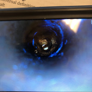
Here is the inside of the aforementioned lead pipe. I used an endoscope to capture some pictures of all the red rod. Looks like the entrance to a cave...
While inspecting the slide, I find that it hangs up on a certain spot. Sure enough, there is a matching set of dents on the outer and inner tubes.
The dent is obscured by the missing lacquer on the outer tube. I tried getting a good picture of the inner tube dent.
I use mandrel that is just slightly undersized to the outer tube's diameter. This pushes up the dent after just a few insertions.
For the inner tube, I use a slide tube mandrel that I made. It measures .458 inches which is a standard size for most trumpets. With the mandrel inserted, I use a small delrin hammer to flatten out any high spots that were created.
I found the upper-outer tube to be too tight. Using an expander and some slide cream, I carefully expand the outer very finely. I walk the expander in and out being cautious not to let it flare out the tube.
These fixes giving a good starting point for the slide later on. Since this slides purpose was to be stationary, it will take some work getting to move as smooth as a trombone's slide.
Disassembling the Slide
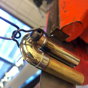
I start with removing the upper outer tube on the slide. I secure it in an expander and heat evenly around the ferrule. One thing I was cautious of was overheating and un-soldering the draw knob. In hindsight, I could of used my draw knob soldering jig to hold it in place. But luckily I had no issues getting the inner tube off.
Next, I setup to remove the upper outer tube on the trumpet. There is a brace between the two outer tubes that will need to be removed as well. Before I start heating any brass, I scrape the edges of the solder joints to break any sealed lacquer.
I use an expander to pull off the slide tube as I heat. I focus my heat first on the areas with the most mass: the valve casing and exapnder. Then I direct the heat to the solder joints of the brace and the valve knuckle. Fortunately, both came off without too much effort.
Finally I remove the brace from the outer tube. In this instance, I was not concerned about burning lacquer as it will later be stripped.
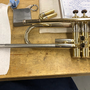
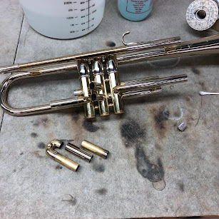
Here are all the pieces laid out. After each solder joint is wiped to tinning, I assemble a mock-up of what the slide will look like once it is soldered.
After a few sessions with the lacquer strip, I manage to remove all the lacquer. This is done for future soldering; the brass and nickel-silver must be bare for solder to adhere.
Shortening the Outer Tube.
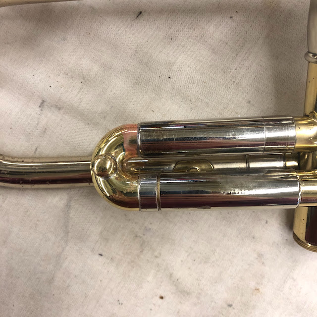
Swapping the outer and inner tube creates an inherent issue with how the slide functions. Due to how the trumpet was built, swapping the slide's counterparts will interfere with how the slide operates when pushed in/out. This creates a gap between the lower ferrule and its outer tube. Unfortunately, I failed to capture an image of this problem before I fixed it. Below is a visual representation.
The upper outer tube is now too long for the slide to close, thus creating a gap in the lower part of the slide. To fix this, the upper outer tube needs to be shortened. (The lower outer tube could be replaced with a longer tube, though I am not sure how this would be practical.)
After taking measurements, I determine that exactly .124" needs to be removed from the end of this tube. This measurement is taken from the size of the gap.
I mark the tube and take it to the lathe to be faced. I use sand paper to help the tube in place and act as a barrier from marring the surface.
For the most precision, I use a dial indicator instead of my mark. I get the lathed set up and face the tube back .124". The end result is a lot of flashing which is cleaned up with a file.
Here is the end result. I assemble the slide to check to see if this alleviated the gap - and it does!
However, in process of fixing the gap I did create a new issue. When I chucked the tube into the lathe, I happened to tighten just little too much. This cause the outer tube to constrict enough for the inner slide tube to no longer fit!
Luckily there is fix for this. Using custom ball nose expanders and a mandrel, I am able expand the inside. This process did take a really long time. I definitely learned my lesson.
Making a Ferrule.
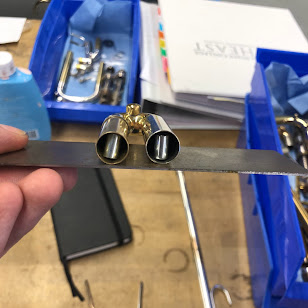
Switching the tubes also creates this issue. The ferrule on the inner tube is too short and cannot cover the solder joint completely. A new one needs to be made.
First, I remove the old ferrule that was soldered on. I measure the amount of tinning on this inner tube and the tinning at the knuckle on the valve casing. This will give a minimum length of how long the ferrule should be.
I will be making the ferrule from an unused, nickel-plated, outer tube that was graciously donated to me by Jason Bystrom (thanks!). I mark the amount needed, then, I get the part setup in the lathe and use a parting tool. I was careful not to over tighten the chuck this time.
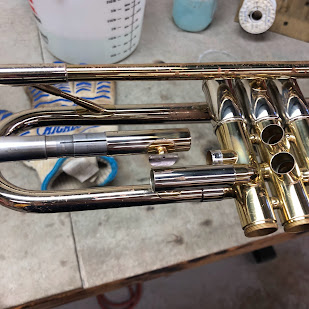
Here is everything assembled though not yet soldered.
Soldering the Slide
Before any soldering can begin, the slide's tubes must be parallel to each other.
I enlarge the area where the outer tube will be soldered since is was too loose. I use a self-made dent ball rod holder and appropriate sized dent ball to achieve this.
Then, using calipers, I check the span of the end of the tubes to the crook. The goal is to have the measurements equal out. This is a tricky process and is helped by...
... A steel plate and some magnets! This really helps keep the tubes in secure position to make small adjustments to their span. A previous student came up with this idea, so all credit goes to them (I think their name was Alisa Smith?).
Before the inner slide can be soldered to the valve knuckle, there is some preparation to be done.
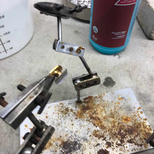
First, the knuckle needs to be adjusted to fit loosely in the ferrule. This will help with aligning the slides in parallel. This is done by strapping the knuckle with 600 grit sand paper.
Next, the knuckle needs to be adjusted very slightly to be in parallel with the lower outer tube. To bend the knuckle, a ground casing mandrel is inserted into the 1st valve for stability. I measured the knuckles opening and found it to be too small for my slide tube mandrel to fit. I quickly went to the lathe and made a custom fit mandrel.
Using some rounding pliers, I grab the slide tube and very slightly bend the knuckle where it needs to go.
Each flexing of the knuckle is checked by inserting the inner slide tube and slide assembly. The ferrule should slide easily over the knuckle without effort.
The slide assembly will be used to hold the inner slide in place as it is soldered to the knuckle.
Done!
The inner slide still needs some slight adjustments to get the slide
moving freely. This is done by pushing on the inner slide in the
direction needed.
Next, the tinning needs to be buffed away by hand. I use some yellow rouge buffing compound and some blue cloth to get into these tight spaces.
Buffed and shiny! Later once the slide ring is soldered, the entire assembly will be buffed and lacquered.
Finally, I use super fine lapping compound to get the slide moving even more smoothly.
The slide is almost complete!
Making the Slide Ring.
The slide ring will be cut from a 1" diameter brass rod. First, I face and turn one end of the stock.
Next I drill the center with a 5/8" bit. This will create the initial opening for the cutting tool to be inserted.
This is the tool that will be used to cut the inner interior of the ring. It is steel that has been cut by a milling machine, sharpened, and then tempered.
The tool is held in the post like so; the operation is similar to that of turning but in this case more material is being removed at a faster rate.
I measure the inner diameter intermittently until the correct measurement is achieved. It does not need to be exact in this case - around .875" was what I aimed for.
I stopped as soon I noticed a bulge forming on the exterior. This is a result of the tool bit not being properly aligned or by the cutting edges not aligning on the same plane. As a result, I stop cutting any further into the part less the ring come off early.
The measurement did not reach what I was looking for. However, I use this moment to learn how I can better cut the ring in my next attempt. Although it would lack room to be used as thumb-ring, it could easily be repurposed for a 3rd slide ring or finger ring in lieu of a finger hook.
I buff the ring with white and then green compound while still on a spinning machine. This is achieved with a soft cloth that has been ragged with compound.
To sever the ring from its body, I use a parting bit. Here I make sure that I am not cutting into the ring itself as it already has the desired thickness.
Here it is fresh off the lathe. There is a noticeable flare leftover from when it was separated. This can later be removed with sandpaper and a de-burring tool.
I went through 2 more iterations until I got the results I wanted. The first attempt is on the right. The second attempt came off the stock before I could cut it off myself (it was too thin anyways). The third attempt went according to plan.
In the future, I may opt to use a thicker stock size - maybe 1 1/8" so that the ring is thicker.
Making the Flange
Apologies in advance for the blurry picture, I am not a very good photographer.
The
flange is what will help bridge the ring to the slide tube. To make a
flange that matches the rest of the trumpet, I will repurpose the old
brace that was removed from the 1st slide.
The flange part of the brace is then hammered flat.
It fits!
Making the "Push Rod"
I use a milling machine with a 5/8" ball nose bit to mill a horizontal radius on one side of the bar stock. This is the side that will be soldered to the flange. I also mill a radius for the ring to sit.
Here are my results.
This is what the components should look like once soldered together. Though not pictured, I round out the flange-side of the push rod to match the other.
Next I prep the pieces to be soldered.
Silver-Soldering the Components
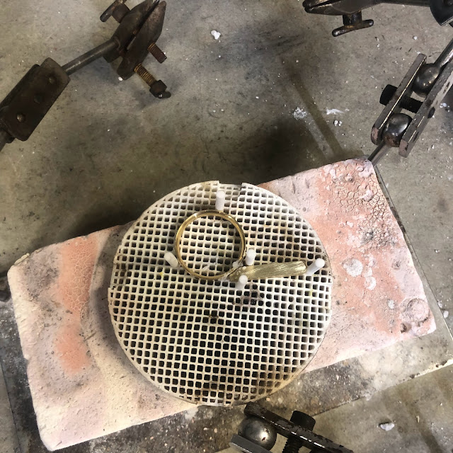
Using a ceramic fixture plate, I position the ring and brass bar to be soldered. I apply some paste flux to joint and use a oxy-acetalyne torch to heat up the parts. Once they start to glow a dull red, I test the silver solder intermittently until it flows.
This my result after removing the heat varnish.
Next, I get the ring aligned with the flange in a jig. I cut a few pieces of silver solder and place them into the joint along with some paste flux. Then, I heat the parts the same as before until the flange settles into place.
This is what it looks like after soldering.
I again remove the heat varnish with phosphoric acid and file away some excess silver solder.
I decided to buff the part before soldering it onto the slide. Removing the tinning is much easier when the component is not yet on the slide.
Soldering the Slide Ring.
I clamp the ring upside down so that gravity helps fill the solder joint. I use lead free solder for a stronger bond.
I manage to get a decent solder joint. There is some tinning that needs to be removed though.
I opted to use Flitz to remove the tinning instead of buffing the slide tube.
With the tinning removed, I hand buff the rest of the slide to prepare it for lacquering. To match the finish of the trumpet, I choose not to get the brass to a mirror finish and instead go for a more "aged" look.
I tape the inner slide tube and make sure to remove any finger prints that I may have added when taking this picture.
With nitrile gloves on, I spray the slide with some Nikolas Clear Lacquer.
After 2 coats, I set the slide on a drying peg and let sit for about 24 hours.
Results
I am happy with my results. Now to see how it looks on the trumpet.
I have learned so much about the trumpet by going through with this project. It turned out to be much more involved and labor intensive than I expected, but I still had a blast seeing it through. Overall, it turned out to be a great learning experience and further grew my interest to do more projects like this in the future.
Thanks for reading.









.HEIC)


.HEIC)









Comments
Post a Comment